Transformer Gain Mic Input
Like Rupert’s classic designs, the Shelford Channel’s mic input uses direct transformer coupling with 15dB of gain in the transformer itself. This extremely sensitive design utilizes the new RN4012 transformer, which spent years in development. The resulting sonic performance allows the mic pre to capture the more forward mid’s and slightly rounded off high and low frequencies of vintage designs like the 1073.
Direct Input
The Hi-Z front panel input uses the same discrete class-A FET with transformer topology as the Rupert Neve Designs RNDI, but it utilizes the new RN4012 input transformer directly into the microphone preamp for gain. This design, delivers exceptional clarity to high-Z sources, with a substantial low-end presence and incredibly smooth high frequencies. The DI also includes a passive THRU output to feed a separate amplifier.
Dual Tap Output
The dual-tap output for the Channel’s RN2042 square-core output transformer creates both high and low headroom outputs without compromising the channel’s performance. The high headroom tap is designed capture a more pristine sound at high levels, avoiding non-linear coloration of the output stage and taking full advantage of the Shelford’s higher voltage design. The low headroom tap however is optimized to allow an engineer to drive the full voltage range of the Channel – adding dynamic tone with these same non-linear “colorations” – without clipping most professional interfaces (Max output level +19dBU). On drums, vocals, guitars and other instruments, this output lets you easily hit the transformer’s “sweet-spot” of non-linear harmonic content, which can bring a recorded performance to life in a way that other effects can’t.
Silk & Texture
Another advantage of the Shelford Channels’ transformer balanced output stage versus vintage modules is the addition of the variable Silk & Texture circuitry, which allows complete control over the harmonic content and saturation of the output transformer. With Silk disengaged, the output is modern and pristine, yet still retains Rupert’s signature larger-than-life transformer sound. When engaged, the harmonic content – predominantly 2nd order and 3rd order with no high order distortion – can be dialed up to several times beyond that found in his vintage units like the 1073. This is further controlled with Silk Red and Blue modes, which emphasize harmonic content generated by the source’s high frequencies (Red) or low frequencies (Blue).
MIC/DI/LINE
Switches between microphone/direct injection input (button out) or line input (button in).
Gnd Lift
This switch separates the direct connection from audio signal ground to chassis earth.
Signal Present LED
This LED is dual function. When green, it indicates “Signal Presence” (a signal level of -20dBu). When red, it indicates 2-3dB below input stage clipping of the Mic/Line stage (+23 dBu while the pre actually clips at +25 dBu).
Mic Gain
This 12-way precision rotary switch controls gain from 0 to 66 dB in 6 dB steps.
Trim
This rotary switch provides further continuous gain adjustment over a range of +/– 6 dB.
48V
This push button switch engages phantom power on the microphone input. Please remember to press the mute button or turn down monitors and headphone sends or the channel the Shelford Channel is plugged into before toggling “+48” (and be especially cautious if you use pre-fader aux sends for headphones).
Phase
This push button switch inverts the polarity of the signal path. It illuminates when engaged. (The symbol “Ø” is often used to denote opposite polarity.)
HPF
The HPF switch engages a 12dB per octave high pass filter. The HPF potentiometer is variable from 20Hz to 250Hz, and can be used to filter out unwanted low frequencies, or in conjunction with the EQ to help shape source material.
Note that engaging the HPF to S/C switch moves the HPF from the primary signal path to the compressor side-chain signal path.
HPF Freq
This control selects the frequency at which the filter begins (-3db) to roll off low frequency signals. It is a 12 dB per octave Bessel filter designed to musically preserve important timing information while cutting low frequency noise and garbage like air conditioning rumble. We may suggest that while recording that the lowest practical setting is generally the safest because it is difficult to try to recover lows with an EQ (6 dB/oct) that may have been chopped off with a filter (12 dB/Oct).
EQ In
This swtich engages all EQ frequency bands except the HPF.
LF
Adjusts up to 15 dB of boost or cut at the selected low frequencies.Cutcan be used as avariable,and perhaps more gentle alternative to using the HPF. Remember to reduce the signal level at the source to minimize the potential for distortion when any of the 3 bands are boosted significantly.
Low Freq
The LOW FREQ rotary switch has 4 positions for selecting one of four corner or center frequencies for the low band EQ section. The frequencies are 35 Hz, 60 Hz, 100 Hz and 220 Hz.
LF Peak
When the button is out, the low-frequency band operates in shelf mode, boosting or cutting below the corner frequency. Above the corner frequency, the amount of boost or cut gradually diminishes at approximately 6 dB/octave. With the HI PEAK button pressed the low changes to peak mode with a bell-shaped boost or cut curve. Between the LF PEAK button and LF FREQ rotary switch, an engineer has 8 tonal variations of EQ shapes to finesse the bottom end, plus the high pass filter can be introduced for further tightening and manipulation.
Mid Hi Q
The resonance or Q of the mid band at maximum boost is typically 2 when the button is out. When the MID HI Q is pressed at maximum boost, the Q narrows to approximately 3.5. The Q widens nicely with less boost or cut as is typical for passive EQ circuits. The Q tends to be slightly wider when the frequency is set lower, and slightly higher for higher frequency selections. The Q is also narrower for cuts than it is for boosts and the mid band is non-symmetrical by design.
Mid
Adjusts up to 15 dB of boost or cut at the selected mid frequencies. Remember to reduce the signal level at the source to minimize the potential for distortion when any of the 3 bands are boosted significantly.
Mid Freq
The MID FREQ rotary switch has 6 positions to select the center frequency of the mid band EQ stage. This circuit utilizes an inductor and capacitors to shape the EQ curve, the same way as Rupert Neve’s console designs of the 70’s. The frequencies chosen are 200 Hz, 400 Hz, 900 Hz, 1.8 kHz, 3.5 kHz and 7.5 kHz. 200 Hz is especially useful for cuts on individual tracks within a dense mix.
HF Peak
When the button is out, the high frequency band operates in shelf mode, boosting or cutting above the corner frequency at approximately 6 dB/octave. Below the corner frequency the amount of boost or cut gradually diminishes. With the HI PEAK button pressed, the high frequency band changes to peak mode with a bell shaped boost or cut curve. The Peak mode utilizes an inductor and capacitor circuit to create the bell-shaped curve.
8k/16k
With the switch out, the center or corner frequency of the high band is 8 kHz. With the button pressed, the center or corner frequency changes to 16 kHz. Between this switch and the HI PEAK switch, you have 4 different EQ curves to finesse the high frequency content.
HF
Adjusts up to 15 dB of boost or cut at selected high frequencies.
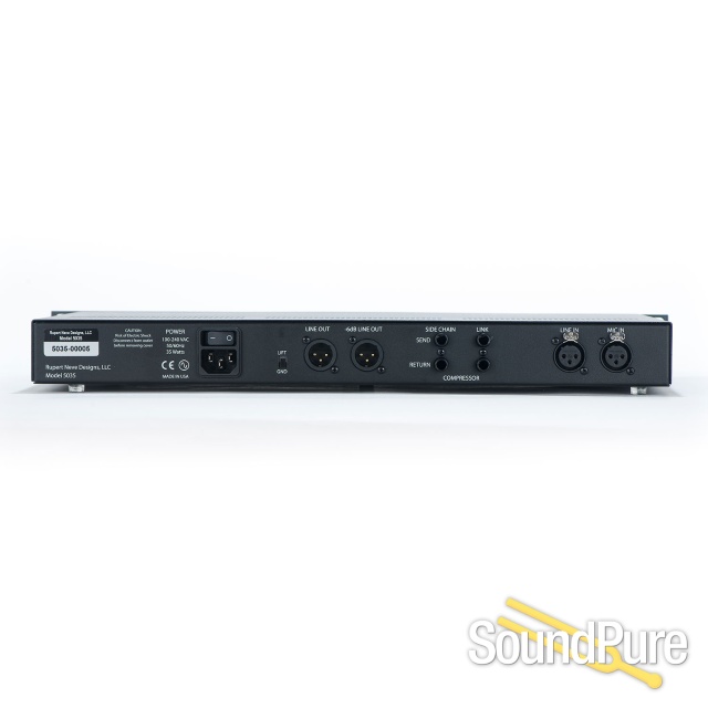
THE SIDE CHAIN INSERT JACKS
These pairs of jacks are only used to perform some fine tuning of the compressor operation. The audio that normally controls the compressor is available on the “SIDECHAIN SEND” jack. One can take this audio and pass it through an external equalizer then return it back to the “SIDECHAIN RETURN” jack. Now changes on the external EQ affect the sensitivity of the compressor. For example, if you cut some low frequencies on the external EQ, then the compressor will tend to not want to reduce the gain as much on bass notes. This is not the same thing as simply boosting lows on an equalizer, because the latter changes the frequency response while the former changes levels. Similarly, one could boost highs (6kHz for example) on the external EQ and cause the compressor to be extra-sensitive to that part of the spectrum which happens to correspond with sibilance (esses). This can act as one type of a de-esser that pulls down the volume of the whole signal if it senses an “ess.”
Comp In
The compressor-limiter section is engaged with this button in. This may be the most useful control on the compressor because it is there for “confidence checks.” In particular, exercise it in both the quietest and the loudest sections of the song.
Watch out for the compressor exaggerating noise and room sound in the quiet sections and chopping off transients and consonants in the loud sections, either of whichsuggestmaybe too much compressor “action.” Conversely, losing quiet phrases or inadvertent clipping might suggest that a little more compression is warranted keeping in mind that you can always do a bit more in the mix but undoing over-compression is not fun and often not even possible.
Threshold
Sets level where the compressor may begin to react from -25 dB to +20 dB. Minimal or no compression is with this control fully clockwise and it gets more sensitive and tends to cause more gain reduction as the knob is rotated counter-clockwise (which may be counter-intuitive to some).
Ratio
Sets the “slope” of the compression from 1.5:1 (minimal) to 8:1 (significant).For exampleif this knob is set for 3:1 then if the signal goes 15 dB over the threshold then it attenuates 10 dB and allows the output to rise 5 dB. In general, low ratios can not damage the music as much as high ratios but high ratios may be more useful to minimize clipping and OL lights in the recorder.
When setting the Threshold and Ratio it is useful to use the VU meter.Howevereven more importantly, you should rely on your ears and use the COMP IN button to perform confidence checks.
SC Insert
This control inserts an external device into the side-chain signal path via the rear panel side-chain insert jacks.
HPF to S/C
This routes the High Pass Filter into the circuit that the compressor uses to determine level, commonly referred to as “the side-chain.” Note that the rest of the circuit and output will not have those lows filtered out. This function tends to be very useful because typical sounds often have more energy in the low octaves and can cause excessive compression. Our ears may tend to associate loudness with mids or high mids for some sounds and one may be wanting the compressor to regulate and smooth perceived loudness. Removing some amount of low frequencies that the compressor “sees” can help especially if one is compressing deeply (-8 dB or more).
Gain
Often referred to as Make Up Gain. Considering the compressor is generally being forced to attenuate louder signals, some method of returning the average level to a volume comparable with the compressor bypassed is desirable. The GAIN control is mostly used for this purpose especially for those of us that depend on comparing compression to bypass. GAIN is often pushed for even more level than “bypass” because it is understood that the compressor should be providing some effective headroom (besides “louder is better” being the oldest trick in the book).
Timing
This six-positioncontrolsadjusts the attack/release speed of the compressor. See the “Timing” section in the Compressor specifications page for timing values.
Link
Links the side-chain control of multiple units for ganged operation, such as would be usedinstereo compression.
Pre EQ
Pushing this button changes the order of where the Compressor is in the circuit.
Blend
This just mixes the dry or raw, uncompressed signal and the compressed signal. Fully counter-clockwise is uncompressed and is very similar to not having the “COMP IN” button pushed in. Fully clockwise is 100% compressor-limiter path, and one can “blend” or mix how much compressed-limited signal vs. dry signal.
Fast
When pressed, alters the speeds up both the attack and release of the selected time constant ofcompressor.
VU Meter
The VU Meter is calibrated to display both average (RMS) output level and compressor gain reduction.


 Rating: 4.9


 919-682-5552