-
Call Us Toll Free888-528-9703
-
Local/International (+1)919-682-5552
- Call Us! Toll Free! 888-528-9703
- Local / International (+1) 919-682-5552

Rupert Neve Designs R6 Color Bundle - 500 Series Rack From Neve
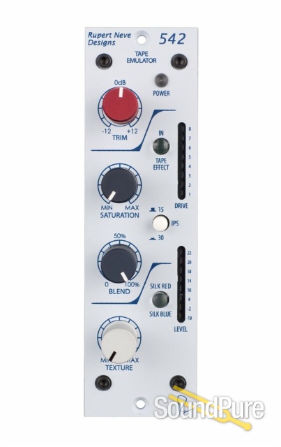
R6 loaded with two 542 tape emulators
$2,099.00
Retail: $2,397.00
"Experience the Difference"
 Payments as low as $47/mo.
Manufacturer's Description from Neve
Power You Can Trust
Power-wise, the R6 has more than 150% the required current for a 6-space chassis to prevent the power rails from failing under a higher-than-expected load. To help monitor and troubleshoot problematic modules, the R6 is equipped with LED current metering to show how much power is being used. The internal power supply itself has been carefully designed and double-shielded to avoid significant magnetic induction in any of the channel positions. With such attention to providing and monitoring power, the R6 helps your modules realize their fullest potential.
Connect Like Never Before
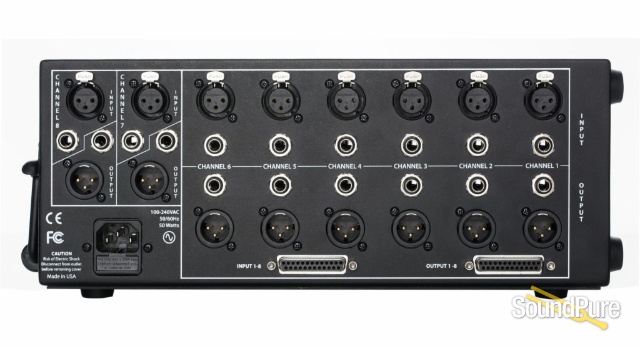
With a plethora of connections available, the R6backpanelispractically apatchbayonits own. The R6 features 8 channels of balanced I/O options including DB-25, XLR and TRS that may be used interchangeably. This versatility is especially handy when you are taking the R6 with you to another environment where you are unsure of the cables available, or if you need to convert DB-25, XLR or TRS connections to another format using the THRU functionality on channels 7-8.
Solid Steel Construction
The chassis is comprised of solid steel with bumpers to support the unit in both horizontal and vertical configurations, and features a collapsable handle for portability. All connectors and fittings are of the highest quality to ensure that the R6 will hold up to many years of use.
A New Level of Confidence in the 500 Series
Because the R6 is built to 500 series specifications, it will work flawlessly with any properly-designed 500 series module you wish to include in it. To help accommodate modules that are slightly out of spec, the R6 has variable-position screw holes to help make the installation process as smooth as possible. The 500 series link function can be enabled in pairs on the R6 using the link jumpers on Channels 1-2, 3-4, or 5-6. Matching blank panels are also available to cover any empty slots.
542 Features:
TAPE IN - Sends the signal through the “True Tape” circuitry, which is affected by the saturation, blend and 15 / 30 IPS controls.
TRIM - Provides +/– 12dB adjustment of level on incoming signal levels, prior to the tape circuit.
SATURATION - Controls the signal level being sent to the "tape head" circuit. As the saturation level increases, the level on the “record” head rises, and the replay gain is reduced so that the overall output signal level remains more or less constant. In a real tape recorder, you would adjust the record and replay gain controls separately - however, in the 542 the record and replay gain controls are coupled so that the overall signal level only varies as the “Tape” saturation level changes. As you approach maximum saturation setting, the output signal level will drop due to the effect of extreme saturation and soft clip.
Additionally, to compensate for low frequency loss at low “record head” levels, the saturation knob also controls a low frequency compensation circuit that boosts low frequencies more at low saturation levels, and tapers off at higher levels. This function can be useful on many sources like bass and kick drum to find the balance between a clean, boosted low end (low saturation) and a denser, more saturated low end (high-saturation).
15/30 IPS - Selects the pre-emphasis / de-emphasis, record / replay tape characteristic. The 15IPS mode has a significant “head bump” in the low frequencies centered around 60Hz, as well as a more pronounced roll of in the high frequencies. The 30 IPS mode is generally a flatter response through the high-end with a “head bump” around 120Hz. See the frequency plots on pages 10 & 11.
BLEND - Controls the mix of pre and post tape signals. This allows the engineer to dial in a subtle amount of the tape effect, to better control the amount of saturation, tone and soft clipping in the post blend signal. As the signal gets more saturated, dialing back the blend can be a great way to impart the feel of tape, while maintaining a similar level of detail and transparency. NOTE: The blend control does not affect the Silk and Texture controls, as that circuitry is located at the physical output of the unit.
SOFT CLIP - A soft clip engages in the “True Tape” circuitry when the drive meter hits 5 (first yellow LED), and becomes more apparent at higher levels. The soft clip can be used as a way to tame overly transient material like drums, and can be controlled further by using the blend control.
SILK / TEXTURE - Pushing the Silk button engages the Silk Red circuit, and pushing it a second time introduces Silk Blue circuitry. Silk reduces the negative feedback on the output transformer, adding harmonic content as the texture is increased. Silk Blue mode features more saturation in the lows and low mids, whereas Silk Red accentuates the saturation in the high mids and highs.
LEVEL / DRIVE METERS - Two eight segment LED bar-graph meters are fitted to the 542 for output level and drive metering. The level meter shows the output level of the 542 before the Silk circuit, and the drive meter reflects the level on the “record head” when the tape effect is engaged. The soft clip circuit is present at Drive levels above 5.
About Manufacturer
Specifications
R6
DC Voltage to Units
+/-16VDC and +48VDC for phantom power
Max Current
1000mA for modules, 150mA for 48V phantom power
Power Requirements
100-240VAC, 50/60Hz, 50 Watts
Weight
9.5lbs
Dimensions
13” long x 7.5”wide x 5.5” high
542
Line Amp Specifications (Measurements with tape circuit disengaged)
Noise
Measured at Main Output, un-weighted, 20Hz-22kHz, Input Terminated 40 Ohms.
Unity Gain Better than -100dBu
Frequency Response
Measured at +10dBu, trim at unity.
Main Output
+/- 0.25dB from 5Hz to 60Khz -2dB @ 120KHz
Maximum Output Level
23.25dBu
Total Harmonic Distortion and Noise:
@ 1kHz, +20dBu output level Better than 0.0025% @ 20Hz, +20dBu output level 0.07% Typical (2nd and 3rd harmonic)
Tape FX Specifications
Noise
Measured at gain Output, un-weighted, 20Hz-22kHz, Input Terminated 40 Ohms.
Saturation @ minimum Better than -100dBu Saturation @ maximum Better than -100dBu
Frequency Response
15 IPS, Input @ -0 dBu -3dBu @ 28kHz Saturation @ minimum 0dBu @ 10Hz +5dBu Peak @ 60Hz
Saturation @ maximum -3dBu @ 20kHz -3dBu @ 12.5Hz +2.4dBu Peak @ 60Hz
30 IPS, Input @ -0 dBu -3dBu @ 120kHz Saturation @ minimum -3dBu @ 10Hz +3.15dBu Peak @ 125Hz
Saturation @ maximum -3dBu @ 100kHz -3dBu @ 12.5Hz
+1.3dBu Peak @ 110Hz
Total Harmonic Distortion and Noise
Refer to sweeps on page10-15 IPS, Input @ -0 dBu 0.4% @ 3kHz to 1% @ 175Hz typical
Saturation @ minimum Greater than 1% below 175Hz typical
Saturation @ maximum 1% at 6kHz typical 0.3% @ 1kHz to 3% @ 50Hz typical
30 IPS, Input @ -0 dBu 1% at 1kHz typical
Saturation @ minimum 0.6% @ 400Hz 5% @ 20Hz typical
Saturation @ maximum 1.5% @ 20kHz to 0.4% @ 1kHz typical 0.4% @ 1kHz to 2 %@ 50Hz typical
Power requirements
Supplied by 500 series rack with 110-125 mA @ +/- 16V DC
